Packaging Petroleum Products
Lubrication, The Texas Company
April 1961
Can Bottoms and Tops
Plain can bottoms and tops are made in a four step operation, as follows:
- Metal sheets are cut into strips of the desired width by scroll shears. (The edges are scrolled or “waved” rather than straight-cut in order to reduce waste during subsequent operations).
- Blanks for tops and bottoms are punched from the scrolled strips by means of double-die automatic end presses.
- The edges of the blanks are bent inward or “curled” by means of curlers as indicated in Figure 7 to facilitate the seaming operation when the end is applied to the can body.
- The future seam is “lined” by placing a thin narrow band of double-seam compound in the curled ends where contact will be made with the can body.
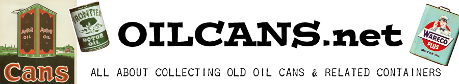
From right to left Figure 8 shows an end press, curler, spiral elevator and liner which are mainly lubricated with the SAE 90 grade of an EP gear oil. The scrolling and blanking machines are the only ones subjected to appreciable working pressures; consequently their main crankshaft and connecting rod bearings must receive frequent lubrication (usually with the SAE 140 grade of an extreme pressure gear oil) to prevent wear and malfunction.
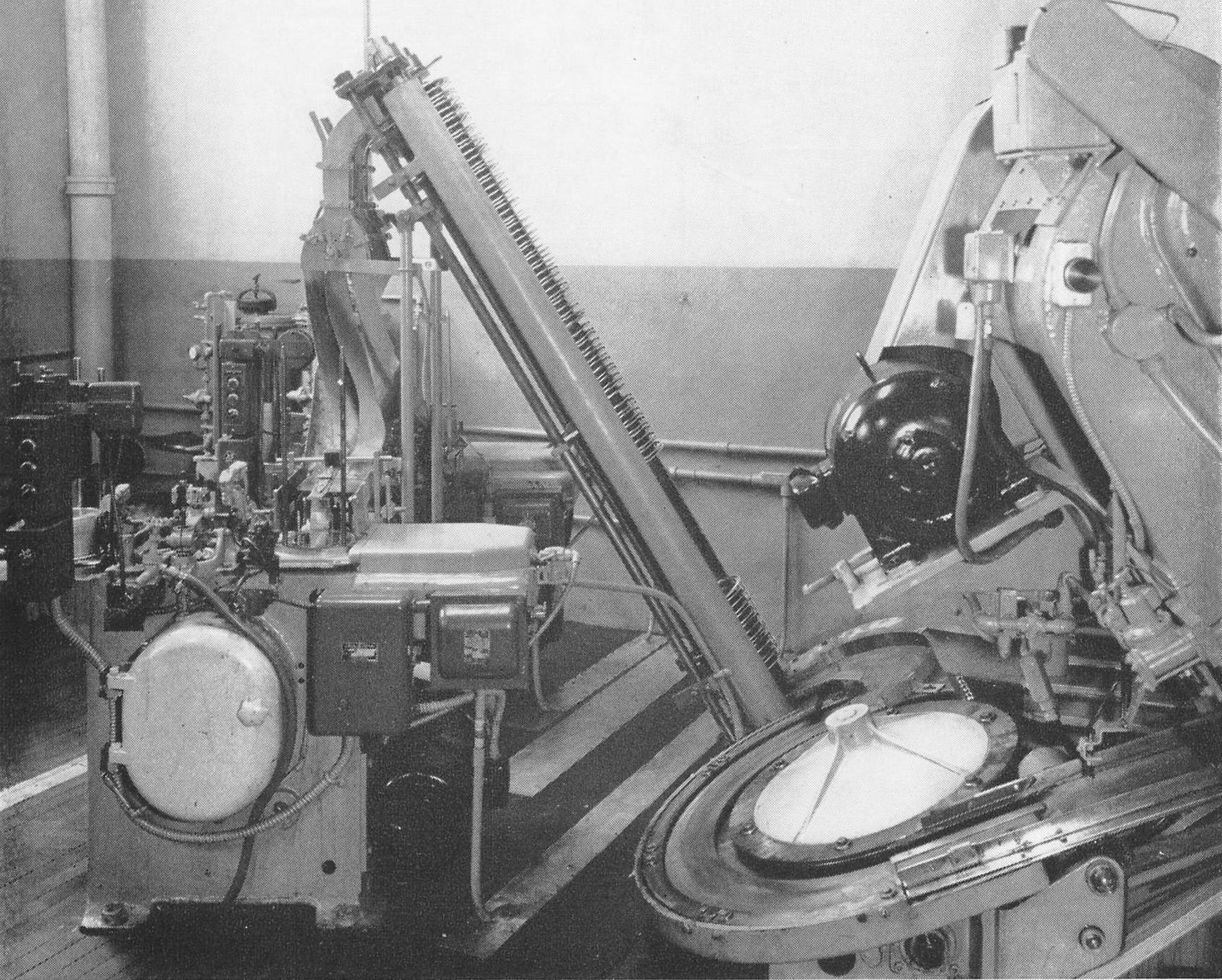
Figure 8 - End press, curler and liner.
Auxiliary Can Top Fixtures
The manufacture of cans for the packaging of petroleum products may be considerably more complicated than the just-described simple assembly of two ends and the body. Complications are caused by the many modifications of the can tops such as screw-top pouring spouts of several designs which are required on the larger cans, together with the application of bails or handles. For example, Figure 9 is an exploded view of the twenty-seven steps required to make a rectangular recloseable gallon can.
Seamer
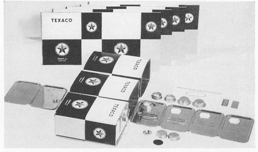
After fabricating a sufficient quantity of can bodies and ends, the process of assembling cans from these parts begins. The first step consists of putting the bottoms on the can bodies which is performed continuously by the seamer, illustrated in Figure 10. Can bodies enter the machine in the right foreground while bottoms are automatically placed on them from the stack at the upper right. The loose assemblies of can bodies and bottoms run under a turret carrying multiple vertical seaming spindles with roller heads which engage the can parts and roll a tight seam in a single turret revolution. A seamer is of substantial construction with the spindles operating on antifriction bearings to prevent any misalignment which would result in faulty seam formation.
Figure 10 - Seamer assembling can bottoms to bodies.
Can Tester
Prior to filling, the bottom-body assemblies of all cans are pneumatically tested in order to reject any with faulty construction which would result in “leakers” after filling. Figure 11 shows a typical 36 bucket tester used for this purpose.
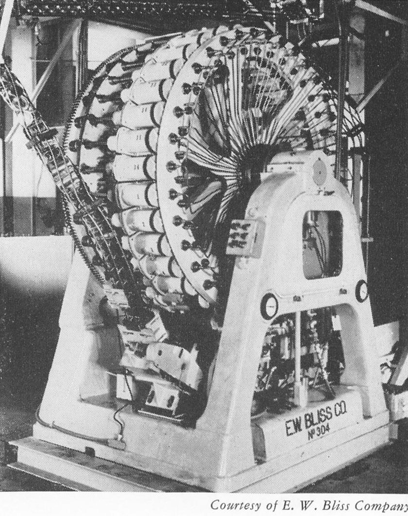
Figure 11 - Thirty-six bucket can tester.
The cans are fed continuously to the unit by gravity through a spiral feed-line chute. In the machine, the flange at each top is clamped against a soft rubber disc. An outer chamber or “bucket” then encloses the can and seals itself on a rubber disc, creating a sealed enclosure around the can. When compressed air is shot into the can at a predetermined pressure, any leakage through it into the bucket raises the pressure in the latter. Even a very slight increase in bucket pressure activates an electro-mechanical rejecting device which literally kicks the fault can out of the machine. The device easily detects pin-hole size holes than can not be seen and its proper functioning is frequently checked by deliberately inserting marked cans know to have pinholes into the feed line.
Can Filling Equipment
Empty cans are light but very bulky, consequently they are filled immediately after manufacture not only to minimize can storage facilities but also to reduce the possibility of dust, dirt or extraneous material getting into the can which would contaminate its oil. The final two steps of filling the can and immediately sealing it by applying its top are both carried out in the unit shown in Figure 12.
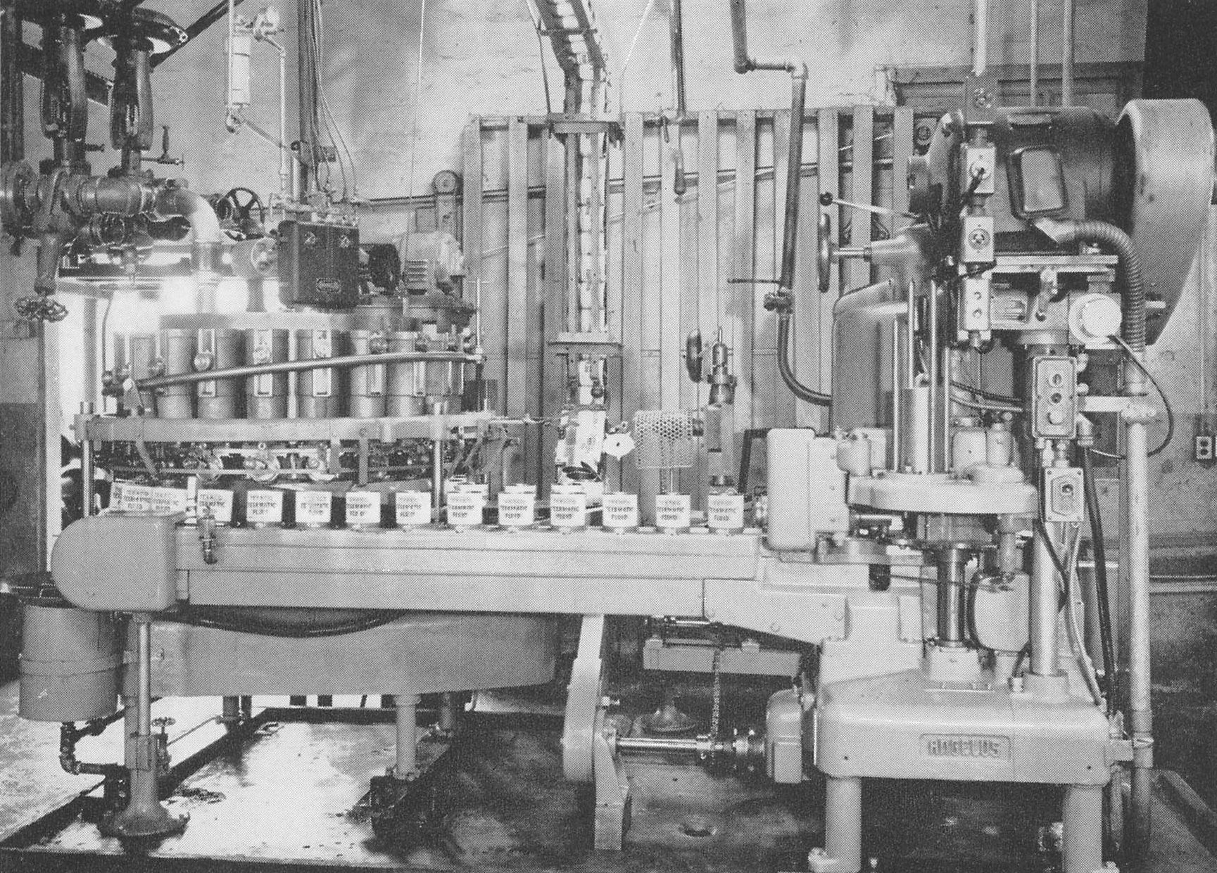
Figure 12 - Can filler and top seamer.
The filling equipment consists of an open cylindrical tank approximately three feet in diameter in which the oil is maintained at a constant level by means of an overhead supply line. Multiple oil dispensing cylinders equipped with rapid opening and closing valves are located around the outside periphery of the oil reservoir. The valves are activated by rollers riding on a circular inclined track. The opening and closing of the valves are adjusted for extremely accurate oil volume delivery by varying the pitch of the valve track. As the cylinders revolve, they are filled from the oil reservoir and emptied into the cans which travel along below them. Since oil flow is a function of its viscosity which in turn is affected by temperature, these variables must be considered in can filling and proper equipment adjustments made to insure full measures. Modern units are capable of filling 18,000 cans an hour. In fact, can speeds are so high that “banking” of curves in the track is required to prevent cans from being thrown off the machine.
The filled cans are fed directly into a “second seamer” shown at the right of Figure 12 which places the tops on the cans and rolls the top seams. This unit has the additional function of stamping the SAE viscosity grade of oil on the can top just before placing it on the can.
The above double operation requires the same perfect synchronization which characterizes other units used in can making. This is obtained by using a single drive with properly designed take-offs for the component parts.
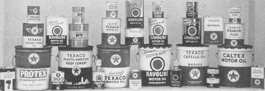
The filled cans are now packed in cartons or otherwise protected for distribution. Figure 13 shows a few of the many sizes and styles of cans used in packaging petroleum oils.
Drums
The manufacture and filling of the five to fifty-five gallon drums are basically the same as for the smaller cans. The larger size, however , dictates the use of welded seams which are formed continuously with a welding wheel. Considerable care must be exercised to insure uniform welding, however, since these containers are not usually tested for leaks. Prior to welding, the body edges are thoroughly cleaned by grinding as shown in Figure 14.
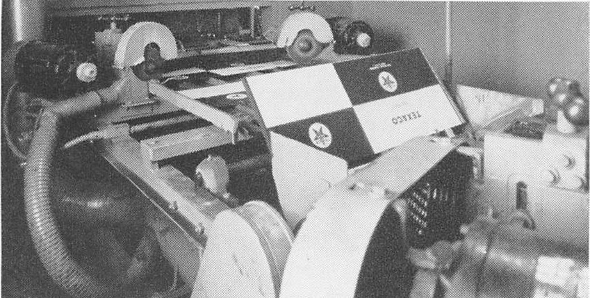
Figure 14 - Grinding edges of body sheets prior to welding.
The lubrication of drum making equipment is comparable to that of the can units. The only critical location is in the bake ovens where unusually high temperatures prevail.
The drum filling operation is much slower and more laborious than for the small cans, since it is accomplished by weighing a predetermined amount of oil into each drum using the equipment shown in Figure 15.
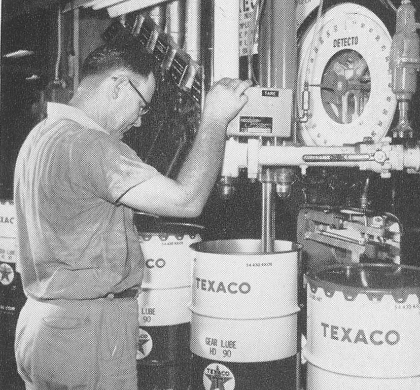
Figure 15 - Drum filling operations.
Package Types
Petroleum products requiring packaging vary from very low viscosity oils to hard, brittle asphalts having very high softening points. Thus the type of packaging is governed by the physical properties of the petroleum product and convenience in ultimate use. Improvement in the ease with which products can be handled by the consumer has given impetus to many new types of packages. Some of these are listed under “Miscellaneous” in Table 1 which shows a few of the large number of packages used for petroleum products. Figures 16 and 17 picture two of the newer packages, both of which illustrate improvement in the ease of product application.
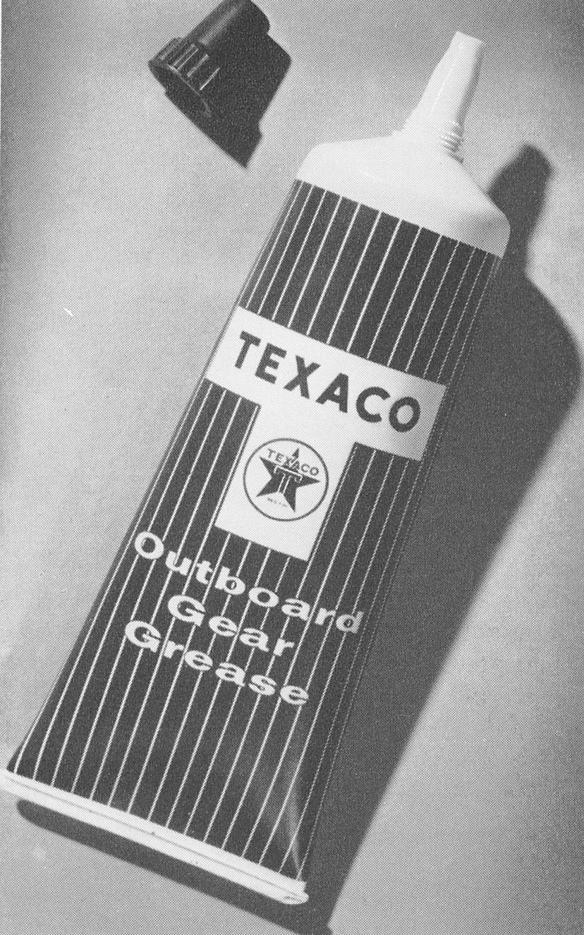
Figure 16 - Plastic tube for outboard motor gear grease which simplifies injection of grease into gear case.
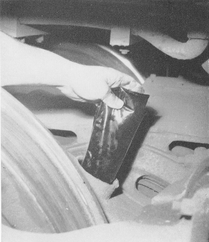
Figure 17 - Old and new methods for applying lubricant to electric traction motor. The plastic lubricant container disintegrates during operation and contributes to gear lubrication.
Due to their low cost, their convenient size and the ease with which they can be removed, fiber cartons are now being used to package roofing asphalts. The filling of these is shown in Figure 18. However, extremely friable high softening point asphalts require no packaging: instead they are cast into 1000 pound cakes which are cooled and then broken into lumps for bulk shipment in gondola cars. The cakes can be readily broken into the desired size by merely dropping them on uniformly-spaced rails like those in Figure 19 which permit the smaller pieces to fall through into the cars.
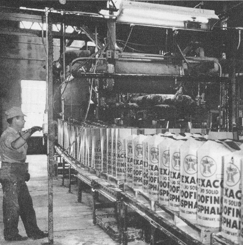
Figure 18- Packaging of roof asphalt.
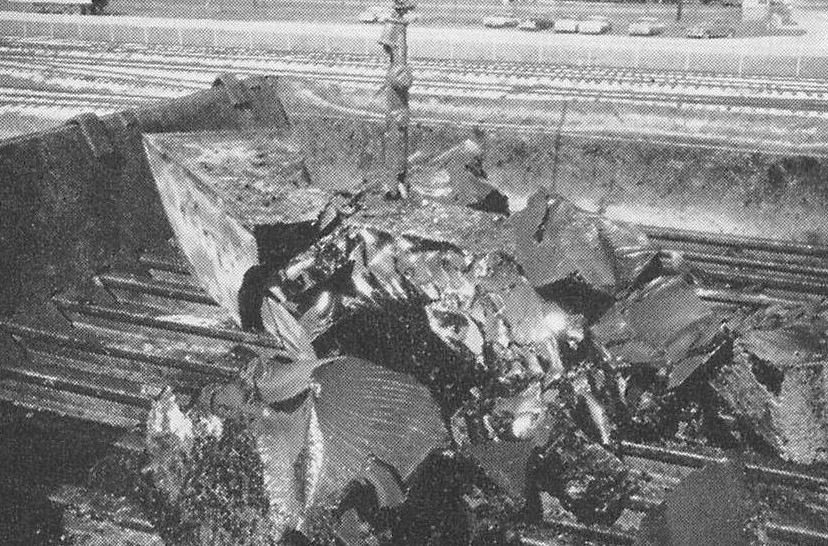
Figure 19 - Breaking cakes of very hard asphalt for bulk shipping.
Lubrication
The importance of adhering to a well organized system of lubrication has been mentioned several times. Individual hand lubrication has been mentioned several times. Individual hand lubrication of the many bearings and gears, which are frequently inaccessible, is not only a tedious chore, but highly dangerous since much must be done while the machines are operating. In order to circumvent this situation many of the units are being equipped with mechanical lubricating systems which feed measured amounts of oil or grease at definite intervals to the parts to be lubricated. Hidden bearings which are grease lubricated through pressure fittings can be insured of receiving regular lubrication by locating the pressure fittings on an accessible panel board and connecting them to the bearings by metal tubing. The pumpability and stability characteristics of a grease may be critical in these units, therefore it is desirable to use a lithium soap multi-purpose grease of the NLGI No. 2 grade.
Summary
Considerable research is underway to improve the packages used by the petroleum industry. This includes the use of new package materials and package design. Considerable attention is being given to packaging which will facilitate handling by the consumer and should result in many improvements in the future.
Though it normally operates at high speeds, packaging machinery is so well designed and of such substantial construction that (excepting ovens) it can usually be lubricated with conventional oils and greases. More extensive use of centralized lubrication systems is indicated however.